introduction to motors
THIS ARTICLE TAKES AN IN-DEPTH LOOK AT AC MOTORS AND THEIR USE
Let's Answer Your Questions:
- What is an AC Motor
- How an AC Motor Works
- The Different Types of AC Motors
- The Many Uses for AC Motors
What Is An AC Motor?
The Powerhouse of Everyday Life: AC Motors Explained
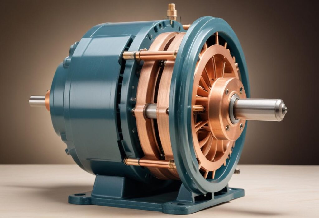
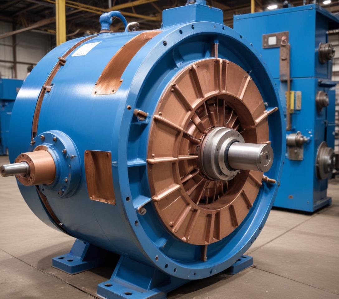
AC motors, or alternating current motors, are the workhorses of our modern world. They transform electrical energy into mechanical power, driving a vast array of applications from pumps and appliances to industrial machinery.
Simple Design, Big Impact
AC motors consist of a stationary stator and a rotating rotor. By supplying the stator with alternating current, a rotating magnetic field is generated. This field interacts with the rotor, causing it to spin.
Two Key Types:
There are two main types of AC motors: synchronous and induction. Synchronous motors precisely match the speed of the rotating magnetic field, while induction motors operate at a slightly slower speed.
Efficiency & Versatility
AC motors are known for their efficiency, quiet operation, and adaptable design. This makes them ideal for powering everything from everyday appliances like fans and heaters to industrial equipment and heavy machinery.
Meeting Global Standards
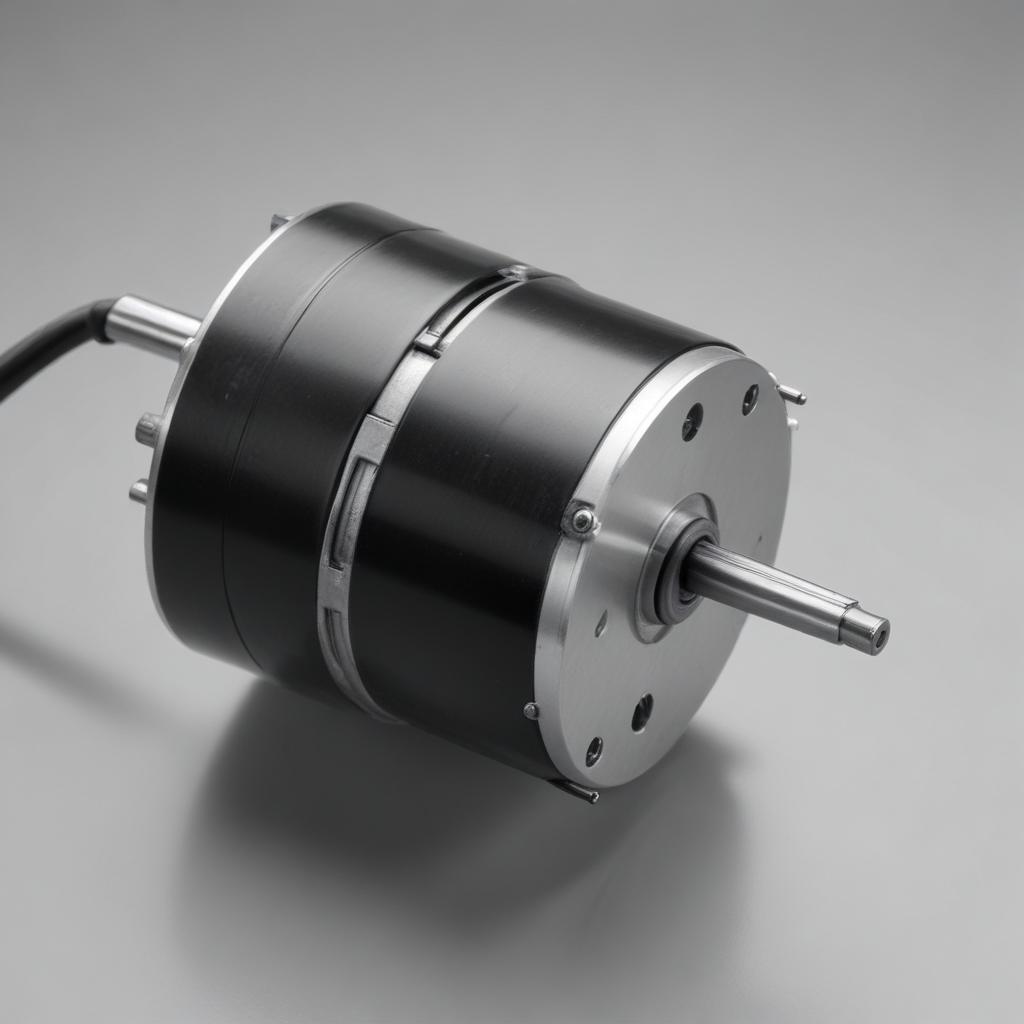
Modern AC induction motors, particularly relevant for industrial applications, meet stringent international standards (IE3 and IE4) for energy efficiency
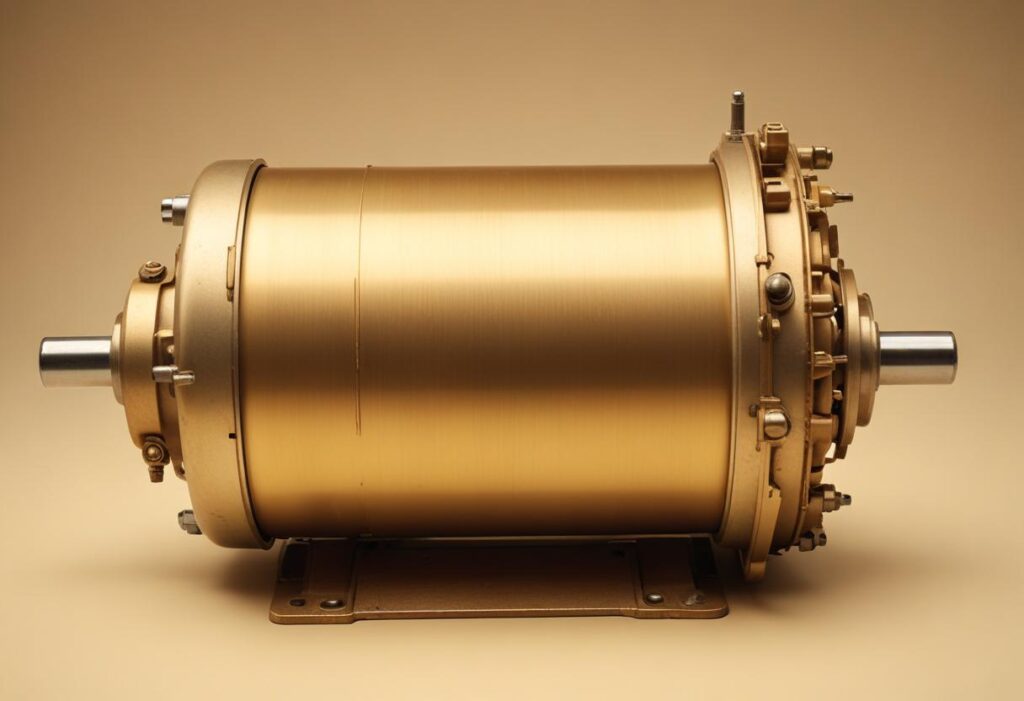
Residential and industrial electricity utilize different phase systems. Homes typically use single-phase or two-phase electricity, while industrial settings rely on three-phase power. This distinction is a major reason why industrial AC motors differ from their residential counterparts.
Finally, AC motors are also known as induction motors because they rely on electromagnetic induction to produce torque. This torque is created by the interaction between the magnetic field generated by the stator’s current and the rotor’s windings
How AC Motors Work
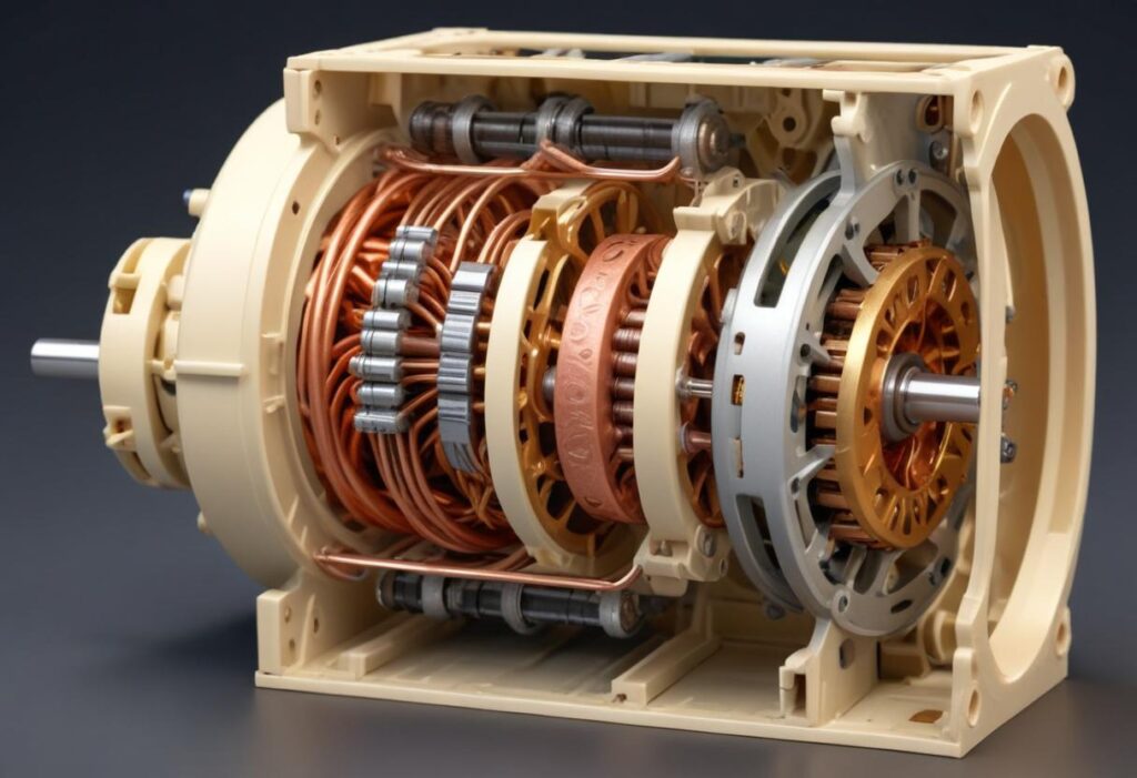
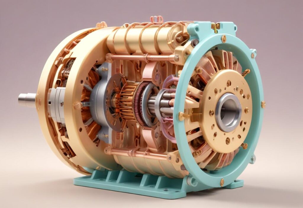
The heart of an AC motor lies in two key components: the stator and the rotor. The stator, a stationary outer drum, houses the winding that creates a rotating magnetic field when supplied with alternating current. This winding acts as both the armature and field winding in an AC motor. Meanwhile, the rotor is the rotating inner portion attached to the motor shaft.
The interaction between these two parts is what generates the motor’s power. As the stator’s magnetic field rotates due to the AC current, an air gap is formed. This rotating flux, at a fixed synchronous speed, induces voltages in both the stator and rotor windings.
AC motors come in a variety of configurations, including single-phase, three-phase, brake, synchronous, asynchronous, customized, and multi-speed options. These variations cater to different work demands. Some are simple and suitable for smaller tasks, while others are robust and designed for heavy-duty industrial applications. A key factor differentiating these motors is the phase of their electrical supply.
start up
AC motors have several starting methods, each with its pros and cons.
The simplest option is the across-the-line starter, using a contactor or switch to directly connect the motor to full power. While convenient, it delivers a high initial current surge (6-8 times normal) that can stress the motor and electrical system. For larger motors, star-delta starting is common. Here, the stator windings are initially connected in a “star” configuration, reducing starting voltage and current. As the motor speeds up, the connection switches to “delta” for full power operation. The autotransformer starter works similarly to star-delta. It uses an autotransformer to initially supply the stator with reduced voltage, limiting the starting current. This method offers greater control over torque and current by adjusting the voltage tap.
Rotor impedance starters connect a variable resistance directly to the rotor through brushes. This resistance starts high, limiting current during startup, and gradually decreases as the motor accelerates. While effective, this method is bulky and expensive. Soft starters are a more sophisticated electronic option. They control both acceleration and deceleration during start-up and shutdown, providing a smoother operation and reducing wear on the motor and connected equipment. Single-phase motors require special attention because their pulsating magnetic field doesn’t generate enough torque for self-starting. Additional mechanisms, like split-phase or shaded-pole starting windings, are needed to initiate rotation.
Stator
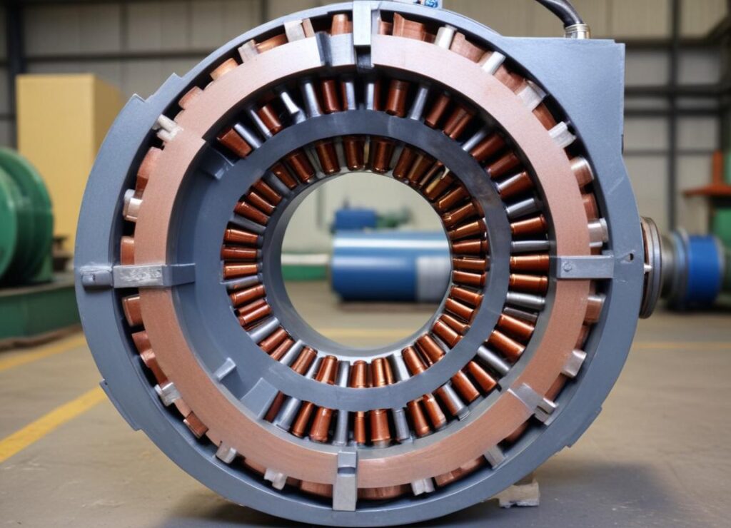
The stator, the AC motor’s stationary part, is responsible for generating the rotating magnetic field. It typically consists of a solid metal axle, a loop of wire shaped into coils, and interconnected sections. The most common type of rotor uses a “squirrel cage” design, but not all AC motors have one.
Electricity is channeled directly to the stator’s outer coils, which are made of copper magnetic wire and wrap around multiple plates extending outward from the center.
Three-phase AC motors, which are more powerful than single-phase motors, have a core and housing containing three separate phase windings spaced 120 degrees apart. These windings, which can number six or twelve in total, are placed on a laminated iron core for optimal efficiency.
Rotor
Unlike a DC motor, the rotor in an AC motor is completely isolated from the external power source. It receives its “power” indirectly, through the magnetic field generated by the stator.
In three-phase induction motors, the rotor comes in two main types: squirrel cage and wound rotor
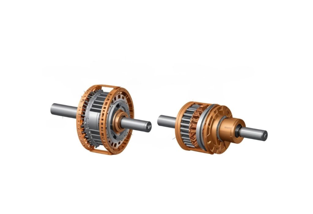
The squirrel cage rotor is the most common design. It consists of conducting bars (usually aluminum or copper) arranged in a cylindrical cage with end rings connecting them at both ends. Different configurations of squirrel cage rotors exist, such as split-phase, capacitor start, and permanent split phase, each with classifications (A, B, C, D, and E) tailored for specific applications.
Unlike the common squirrel cage rotor, wound rotor motors offer greater control over speed and torque. These “slip ring” motors, as they’re also called, share the same basic components of a typical AC motor but are always designed for three-phase operation.
The key difference lies in the rotor itself. Instead of the simple bars of a squirrel cage, a wound rotor has a cylindrical core wrapped with wires, mimicking the stator’s windings. The ends of these wires connect to slip rings mounted on the output shaft. Brushes then connect these slip rings to an external variable speed resistor. By adjusting the resistance, you can influence the motor’s speed and torque, providing greater operational flexibility.
Wound rotor motors, also known as slip ring motors, are classified as asynchronous. This means the rotor’s speed never quite matches the speed of the rotating magnetic field generated by the stator – there’s always a “slip” between the two. As the motor operates, the currents induced in the rotor’s windings actually weaken the stator’s magnetic field slightly. This interaction allows for precise control over the motor’s rotation. By adjusting the resistance connected to the slip rings, you can influence the amount of slip, giving you the ability to fine-tune both torque and running characteristics for specific applications.

